Timing Analysis With OpenSTA
Using an Ideal Clock
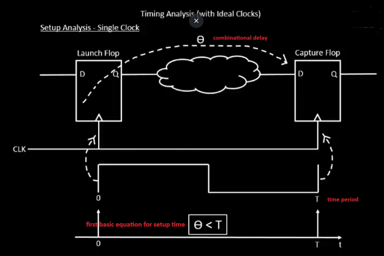
Before the clock tree is built, we can perform timing analysis using an ideal clock to understand key timing parameters. This serves as a baseline for evaluating the circuit’s behavior before CTS (Clock Tree Synthesis) is applied.
The specifications are as shown in the figure — for example:
- Clock Frequency (F): 1 GHz
- Clock Period (T): 1 ns
Later, a similar analysis can be performed using the real clock after the clock tree is implemented, allowing us to measure actual skew, latency, and path delays.
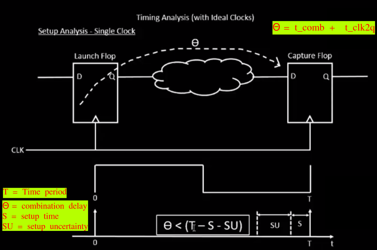
- : The combinational delay — this includes the clock-to-Q delay of the launch flip-flop plus the propagation delay through all logic gates between the launch and capture flip-flops.
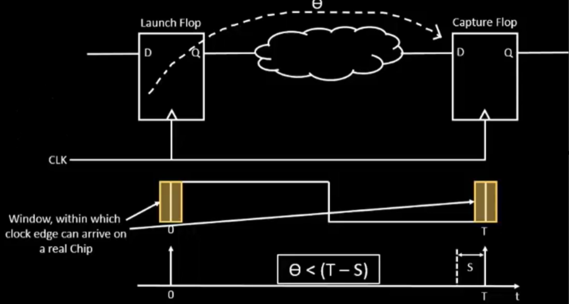
- T (clock period): Also known as the required time, this is the total time allocated for the signal to propagate from the launch edge to the capture edge — typically defined by the inverse of the clock frequency.
- S (setup time): The minimum time before the active clock edge at the capture flip-flop during which the input signal must remain stable. For example, in the circuit shown below, the signal must arrive and settle at the input of Mux 2 before the next rising edge of the clock. Therefore, the delay introduced by Mux 1 must be accounted for in the setup time calculation.
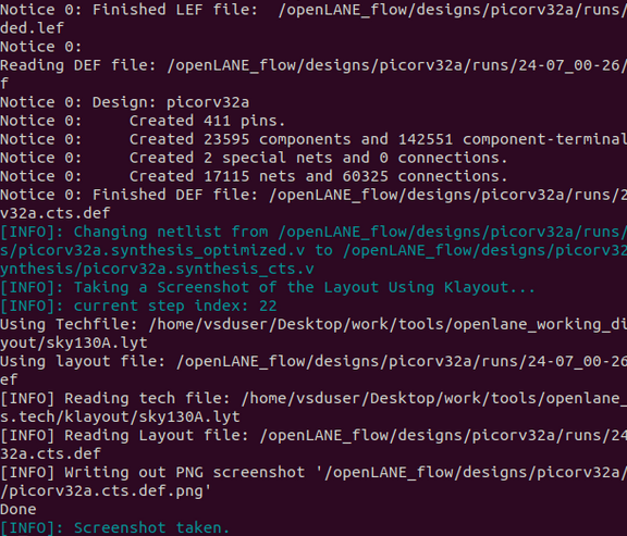
Using a Real Clock
- Setup time:
- = data arrival time
- = data required time
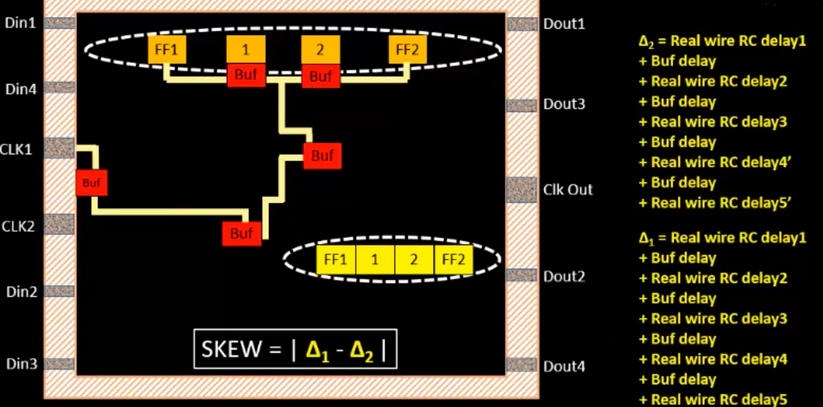
- Skew:
- Hold time:
Once the clock tree is built, timing analysis is performed on the actual (non-ideal) clock network. Two key delays are introduced:
- : Clock network delay to the launch flip-flop
- : Clock network delay to the capture flip-flop
These values are critical in determining whether the design meets timing at the given clock frequency.
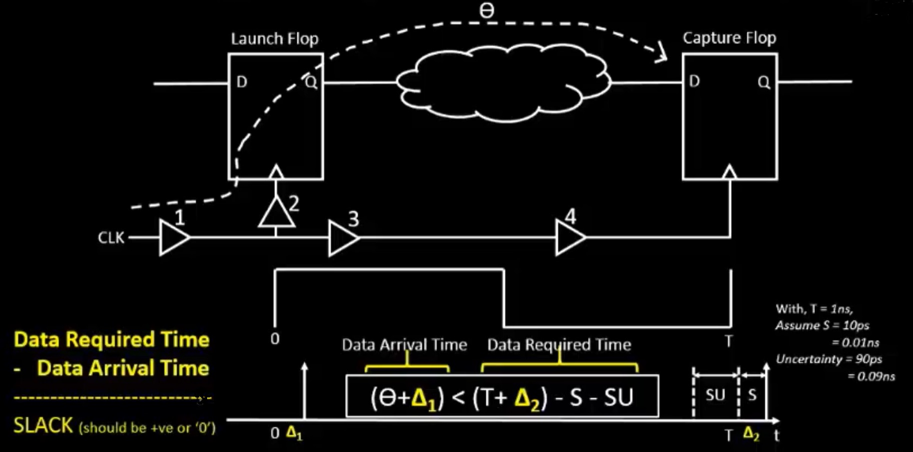
Setup Timing and Slack
Slack = Data Required Time − Data Arrival Time
A design is considered timing-closed if slack ≥ 0 — meaning the data arrives on time or early enough.
If slack < 0, a setup violation occurs, indicating the data is arriving too late to be reliably captured, and the design will not operate correctly at the target frequency.
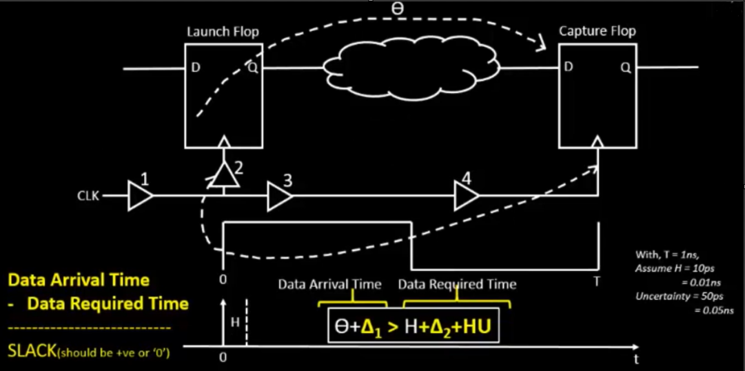
Hold Timing Analysis Using Real Clocks
Hold time refers to the minimum duration that data must be held stable at the launch flip-flop’s output after the clock edge, to ensure it is correctly captured by the destination flip-flop.
Unlike setup analysis (which spans two consecutive rising edges), hold analysis happens on the same clock edge for both flip-flops.
A hold violation occurs when:
- The combinational path is too fast
- Clock buffer delays cause the capture flip-flop to receive the clock edge too early
- The data changes too quickly, violating the hold requirement of the destination flip-flop
- Clock period (T) and setup uncertainty (SU) are irrelevant in hold analysis (since the same rising clock edge is used at both launch and capture flops)
- Instead, focus is placed on:
- Combinational delay
- Clock path skews ( and )
- Hold time requirement of the capture flop
If the path delay is too short, it can lead to incorrect or unstable data capture, even if setup timing is met.
Jitter and Uncertainty
What is Jitter?
In most digital systems, clock signals are generated by a PLL (Phase-Locked Loop), which is designed to produce clock pulses at regular intervals — ideally at 0, T, 2T, 3T, ..., where T is the clock period.
However, in reality, even high-quality PLLs exhibit some amount of timing variation, known as jitter.
Jitter refers to the short-term fluctuations in the exact timing of clock signal transitions. Instead of arriving exactly at T nanoseconds, a clock edge might arrive slightly earlier or later due to jitter, causing deviations from the expected timing.
This variation can affect both clock and data signals, and becomes especially critical in high-speed or tightly timed designs, where even small timing errors can lead to setup or hold violations.
What is Uncertainty?
- SU (Setup Uncertainty): Setup uncertainty arises from jitter — the short-term, unpredictable variation in the clock period caused by non-idealities in the PLL (Phase-Locked Loop). This uncertainty reduces the effective time available for data to propagate and settle before being captured, and must be accounted for during timing closure.
Running the Post-Synthesis Timing Analysis via OpenSTA
Make sure that you already did the following in the docker + OpenLANE terminal environment:
prep -design picorv32a
set lefs [glob $::env(DESIGN_DIR)/src/*.lef]
add_lefs -src $lefs
set ::env(SYNTH_SIZING) 1
run_synthesis
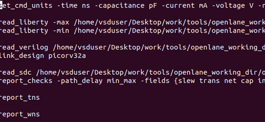
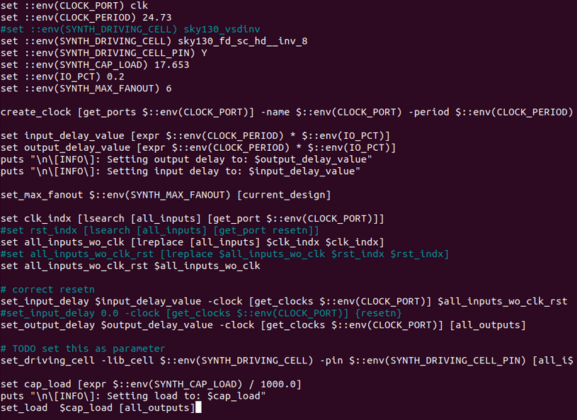
pre_sta.conf File Contents
There should be a pre_sta.conf file in the OpenLANE directory.
Run nano pre_sta.conf to view its contents:
my_base.sdc File Contents
There will also be a my_base.sdc file in the /openlane/designs/picorv32a/src directory. cd into the directory and view the file contents:
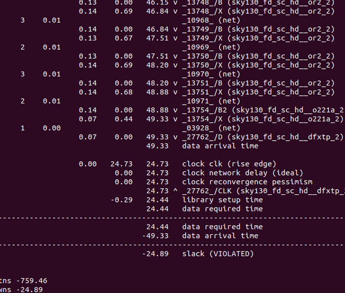
Run STA
Make sure you are in the OpenLANE directory. Then, run the following:
sta pre_sta.conf
Uh oh. Looks like our slack is really bad:
Identify any gates that drive too many fanouts with too little strength. You may have found an OR gate like this! (Hint: try it yourself!)
You can replace the weak gate and then re-run the analysis:
report_net -connections _11672_
help replace_cell

# this replaces the cell
replace_cell _14513_ sky130_fd_sc_hd__or3_4

# generate a timing report
report_checks -fields {net cap slew input_pins} -digits 4
You will notice that the slack is reduced:

It wasn't a huge improvement, but it's a start! Continue looking for problematic gates, optimizing them until the slack is significantly reduced. Afterwards, run cp picorv32a.synthesis.v picorv32a.synthesis_old.v to replace the old netlist with the new one.
Write the verilog with write_verilog /home/vsduser/Desktop/work/tools/openlane_working_dir/openlane/designs/picorv32a/runs/<date>/results/synthesis/picorv32a.synthesis.v. Make sure to replace <date> with the run you are using.
Clock Timing Synthesis (CTS)
Run run_cts to start the CTS.